Incinerator 300 kg/hr Burn Capacity (min. 1200 kgs. Waste Feed Capacity per day) (Power Supply 380V, 50Hz, 3Ph)
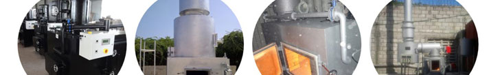
Incinerator main unit main body (primary chamber, secondary chamber, mix-combustion chamber
Filter Chamber
Chimney
PLC Panel
Oil Tank
Combustion burner
Wind Tube
Oil Tube
Filter brick
Ash clean tool
Blower
Furnace gate
Especificações Gerais 6 mm plate steel sheel construction
11cm 1400°C refractory Liner
temperature controlled Burners
secondary combustion burners
interlock switch on load doors
separete ash door
one secondary residence @ 1000°C
400°C silicone Based finish paint
alloy temperature sensor
factory wired and tested
Capacity 20kg/hr
primary Chamber 1607 L
Hearth area 1.36 aq.m
Secondary Chamber 694L
Primary burner (oil) 420.00btu
Secondary burner (oil) 900,000btu
Secondary combustion 1/6 hp
Exhaust stack 46cm x 6m
Electrical service 220/50
System weight 5,700kg
Dimension “D” 152cm
Doad port height e 60x60cm
Ash port height e 36x36cm
General Specifications 6mm plate steel sheel construction
11cm 1400 ° C refractory liner
temperature controlled Burners
secondary combustion burners
interlock switch on load doors
separete ash door
one secondary residence @ 1000 ° C
400 ° C silicone based paint finish
alloy temperature sensor
factory wired and tested
Capacity 20kg/hr
primary Chamber 1607 L
Hearth area 1:36 aq.m
Secondary Chamber 694L
Primary burner (oil) 420.00btu
Secondary burner (oil) 900,000 btu
Secondary combustion 1/6 hp
Exhaust stack 46cm x 6m
Electrical service 220/50
System weight 5.700 kg
Dimension “D” 152cm
Doad port height and 60x60cm
Ash port height and 36x36cm
Conduits for steam or water with a temperature of >60°C must be equipped with insulation material.
Based on a heat conductivity of 0.035 W/mK, the thickness of the insulation material should be 2/3 of
the diameter of the pipe. Conduits for pressurised air and condensate should be equipped with dirt catchers.
Adjustment and safety valves should be designed according to local safety standards.
Display, steering and measurement
The steering of the treatment process should be fully automatic, a manual control shall not be possible.
Display, steering and measurement
The steering of the treatment process should be fully automatic, a manual control shall not be possible.
The control should however allow the step-by-step processing by an authorised person. An intervention
with a stroke switch should be only possible in serial-circuit processing with a key-switch. During the
stroking the automatic process must be switched off and it should not interfere with any functions relevant for safety.
All instruments and indicating devices shall be located in a position where they can be readily viewed
All instruments and indicating devices shall be located in a position where they can be readily viewed
by the operator under normal operation of the treatment unit and shall be identified as to their function.
Unless otherwise specified instruments and gauges shall be readable by normal or corrected vision
from a distance of (1,00 ± 0.15) m and with a minimum external illumination of (215 ± 15) lx.
“The Treatment Equipment shall be equipped at least with the following instruments:
treatment chamber temperature indicating instrument;
treatment chamber temperature recorder;
treatment chamber pressure indicating instrument;
treatment chamber pressure recorder;
jacket pressure indicating instrument (if the treatment unit is fitted with a jacket); and
steam pressure gauge (if a steam generator is incorporated into the panelling).”
“The Treatment Equipment shall also be provided with at least the following indicating devices:
visual display indicating “”door locked””;
visual display indicating “”in progress””;
visual display indicating “”cycle complete””;
visual display indicating “”fault””;
indication of the operating cycle selected;
operating cycle counter
operating cycle stage indication.”
Pressure steering and gauge instruments: The steam supply pipe, the pressure vessel and the steam
jacket should be equipped with a pressure gauge. For the control process, absolute pressure regulators
should be used. The treatment chamber pressure indicating instrument shall be graduated in kilopascals
or bars, with a zero reading at absolute vacuum or ambient pressure respectively.
Steering instruments and heat gauge for the process temperature: At least two independent temperature
Steering instruments and heat gauge for the process temperature: At least two independent temperature
sensors shall be provided. The measurement range should be 20°C – 160°C. The temperature sensor
shall have a response time T< 5 s when tested in water and shall have an accuracy of at least ± 1 % over the scale range.
Time measurements – clocks: The effective treatment time depends on the treatment temperature.
Time measurements – clocks: The effective treatment time depends on the treatment temperature.
The treatment time for a specified treatment temperature should be controlled by a process clock and fixed.
Only authorised personal shall be allowed to change the treatment time for a specified treatment temperature.
Treatment cycle recorder: The recorder shall be independent such that the measuring chain as well as
Treatment cycle recorder: The recorder shall be independent such that the measuring chain as well as
value data processing and printed values are separate from the automatic controller. The recorder
should be a temperature compensated dotted line recorder. Records shall include the limiting values
for all cycle variables throughout the operating cycle. The printing of data shall be sufficient to ensure
that any deviation outside permitted tolerances can be identified. The recorder shall produce a record
which shall be readable when stored in defined conditions for a period of not less than 10 years.
Measurements for documentation: Gauges used to document the process cycle should be separated,
Measurements for documentation: Gauges used to document the process cycle should be separated,
the measurement for the temperature should be at the most inconvenient place in the outlet of the
pressure vessel (for vacuum systems) or at the bottom in the condensate (for chambers without steam jackets)
Process temperature and holding time
The treatment temperature band shall have the lower limit defined by the treatment temperature and an
Process temperature and holding time
The treatment temperature band shall have the lower limit defined by the treatment temperature and an
upper limit of + 4K. Throughout the holding time (period for which the temperatures at the reference
measurement point and the load are held within the decontamination temperature band) the temperature
measured at the reference measurement point of the treatment unitl chamber shall not be lower than 121°C (TDes 0+4).

Nanjing Clover Medical Technology Co.,Ltd.
Tel: +86-25-8461 0201
Mobile: +86-13813931455(whatsapp/wechat)
Website: www.hiclover.com
Email: [email protected]
Email: [email protected]
Website: www.hiclover.com
Email: [email protected]
Email: [email protected]
| Items/Model | TS10(PLC) | TS20(PLC) | TS30(PLC) | TS50(PLC) | TS100(PLC) |
| Burn Rate (Average) | 10 kg/hour | 20 kg/hour | 30 kg/hour | 50 kg/hour | 100 kg/hour |
| Feed Capacity(Average) | 20kg | 40kg | 60kg | 100kg | 200 kg |
| Control Mode | PLC | PLC | PLC | PLC | PLC |
| Combustion Chamber | 100L | 210L | 330L | 560L | 1200L |
| Internal Dimensions | 50x50x40cm | 65x65x50cm | 75x75x60cm | 100x80x70cm | 120x100x100cm |
| Secondary Chamber | 50L | 110L | 180L | 280L | 600L |
| Smoke Filter Chamber | Yes | Yes | Yes | Yes | Yes |
| Feed Mode | Manual | Manual | Manual | Manual | Manual |
| Voltage | 220V | 220V | 220V | 220V | 220V |
| Power | 0.5Kw | 0.5Kw | 0.5Kw | 0.7Kw | 0.7Kw |
| Oil Consumption (kg/hour) | 5.4–12.6 | 7.8–16.3 | 10.2–20 | 12.1–24 | 14–28 |
| Gas Consumption (m3/hour) | 6.2–11.4 | 8–15.7 | 9.8–20 | 9.9–26.1 | 10–32.2 |
| Temperature Monitor | Yes | Yes | Yes | Yes | Yes |
| Temperature Protection | Yes | Yes | Yes | Yes | Yes |
| Oil Tank | 100L | 100L | 100L | 100L | 200L |
| Feed Door | 30x30cm | 45x40cm | 55x50cm | 70x55cm | 80x60cm |
| Chimney | 3Meter | 3Meter | 5Meter | 5Meter | 10Meter |
| Chimney Type | Stainless Steel | Stainless Steel | Stainless Steel | Stainless Steel | Stainless Steel |
| 1st. Chamber Temperature | 800℃–1000℃ | 800℃–1000℃ | 800℃–1000℃ | 800℃–1000℃ | 800℃–1000℃ |
| 2nd. Chamber Temperature | 1000℃-1200℃ | 1000℃-1200℃ | 1000℃-1200℃ | 1000℃-1200℃ | 1000℃-1200℃ |
| Residency Time | 2.0 Sec. | 2.0 Sec. | 2.0 Sec. | 2.0 Sec. | 2.0 Sec. |
| Gross Weight | 1500kg | 2200kg | 3000kg | 4500kg | 6000kg |
| External Dimensions | 140x90x120cm | 160x110x130cm | 175x120x140cm | 230x130x155cm | 260x150x180cm |


